Pt. 1: Practical Refinements
Motivation
With the stock of original parts from Ian now fully used up, this presented a natural point to revisit the design. Building each unit by hand over the past years has given me a good sense of where small changes could simplify production without altering the proven functionality.
What started as a simple microcontroller change turned into a broader refinement of the design to make assembly easier, improve handling, and future-proof the hardware while keeping the core unchanged, and increasing performance in some areas.
Microcontroller and Firmware
The microcontroller has been changed to the AVR64DB48, now running at a higher clock speed and offering improved analogue functionalities.
Large parts of the firmware were rewritten, resulting in cleaner and faster code. The user interface now feels noticeably more responsive, and the serial connection is more robust, with supported baud rates extended up to 230400 and fully compatible with the IUSL.
Power Input and Charging
The v1 units of the PDVS 2 Mini use a daughterboard mounted at a 90° angle on the lower side of the unit for the charging functionalities and DC power input. The daughterboard is mounted using soldered angled pin headers, which made assembly difficult, as the two boards had to be aligned at exactly 90°, soldered, and then the longer pins on one side of the headers had to be cut.
There are a total of 8 pins, so 8 signals could be transferred between the boards, which does not allow for changes without larger modifications to the design. One of the limitations of the design is that the incoming voltage from the charger is only measured indirectly via activity of the charging IC, leading to the "OVER" charging current warning when running the unit without batteries from the DC input - not harmful, but annoying.
The v2 fixes this issue (among others) by independently measuring the battery / system, and DC input voltages.

The second functionality involving the daughterboard on the v1 units is the DC input jack, which has limitations as well: it uses a small (and somewhat uncommon) 1.35x3.5 mm plug, of which only a certain type with a small outer diameter can be used due to space constraints, as the connector shell has to pass through the front cover before plugging into the main PCB. Unplugging can also be difficult, as the outer shell can not be gripped well. Angled plugs can not be used at all or are not available in the needed form factor.
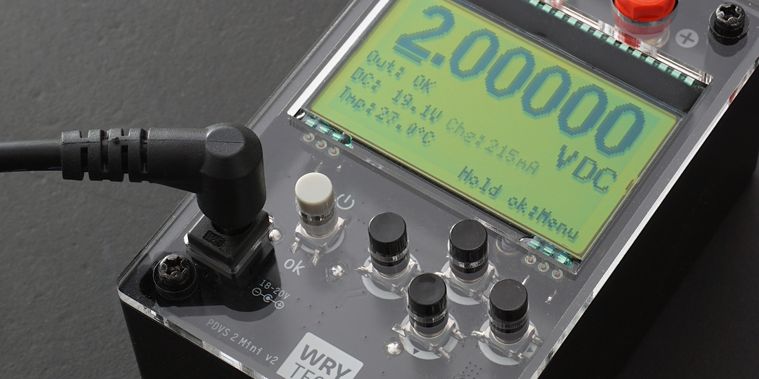
Here, v2 uses a standing 5.5x2.5 mm jack in the same position. This is a much more common size, and since the jack protrudes slightly through the front panel (about the same distance as the banana jacks and button caps), any fitting connector and cable — including angled ones — can be used. Mechanical stability is also increased due to the larger size of the inner pin and larger soldered area compared to v1.
User Interface Changes
Instead of six buttons, v2 only has five, as the main power switch and ok button are now combined.
In v1, the power button only serves to turn the unit on and off, and an accidental touch can accidentally shut it down. Now, the two buttons and their functionality are combined into one: turning the unit off is done via the main menu, and requires a slightly longer press than the navigation inputs to other submenues, effectively eliminating accidental shutdowns.
Additionally, the saved space allows for more efficient placement of the DC power jack next to the button.
PCB Layout Refinements and Manufacturability Improvements
With the microcontroller updated, various other layout refinements have been implemented to maximize the ground plane area on the upper layer, including using both switch contacts for the buttons in parallel for all switches, among other small improvements.
Manufacturability has been improved in various ways as well, as highlighted in the picture below:
- In v1, the total width of the PCB (and thus the housing) is determined by the width of the two battery holders placed side by side. This often leads to problems in assembling the units, as the highlighted green prongs were frequently tilted slightly, resulting in misalignment and making the total width too large to fit the housing properly. Fixing this required matching or reworking the holders.
By offsetting the holders and moving them slightly toward each other, this issue is eliminated. In addition, room is made for the DC jack.
- The highlighted blue area contains the ceramic DC input fuse and PTCs on supply rails. This area remains accessible in the finished product to enable simple repairs if needed. So far, no replacement of these components has been necessary in any product sold, but I consider it good practice to keep these things in mind.
- The mounting holes, which are non-plated in v1, have been changed to plated-through holes with annular rings. This was done to create a more defined contact area with the housing and spacers, provide better wear protection, and offer a visual upgrade as well.

Summary
The changes shown here exemplary are focused on refining the product for long-term consistency and easier production. Nothing fundamental has been altered - the PDVS 2 Mini remains fully true to its original concept. The updates serve to make assembly more straightforward, the user interface a bit more polished, and handling a little more robust in daily use.
